While EAGLE includes a fair number of PIC microcontroller footprints in their standard libraries, the selection is limited compared to Microchip’s full catalog. If you’re looking for a more obscure part (like the PIC16F1947, for example), you’re on your own. There is also no official Microchip-supplied EAGLE library.
They do, however, offer an alternative – and it applies to more than just microcontrollers. Read on to learn how to generate component symbols and footprints for almost any part that Microchip offers, and with a minimum of fuss.
Ultra Librarian
 Rather than provide EAGLE libraries directly, Microchip supplies footprints and symbols in a proprietary interchange format (.bxl). From those files, a program called Ultra Librarian (produced by Accelerated Designs, Inc.) will produce footprints and symbols for most major CAD/CAE packages. The full version is quite expensive for a hobbyist, but Microchip has fortunately partnered with the company to provide a limited version for free.
To install, download the Ultra Librarian Install Program from Microchip’s site. Note that this is a Windows program; if you’re on a Mac, you’ll need Parallels or Fusion and a copy of Windows. The whole package, from the installer to the program itself, gives the impression of a bad mid-90’s VB app – but it does work!
Once installed, you can download collections of bxl files directly from Microchip. You can then use Ultra Librarian to convert from .bxl to an EAGLE script that will create the part in your library. The resulting parts are not perfect, but they’re not hard to correct.
So how is it done?
Step 1: Load the Data
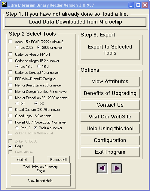
 Downloading and uncompressing the appropriate collection(s) from Microchip’s site results in a directory full of clearly-named blx files. Once you have these, run the program and click the giant button at the very top of the window (“Load Data Downloaded from Microchip”) to select one to work with. Note that you can only select one file at a time; there doesn’t appear to be a way to generate multiple footprints in a single operation.
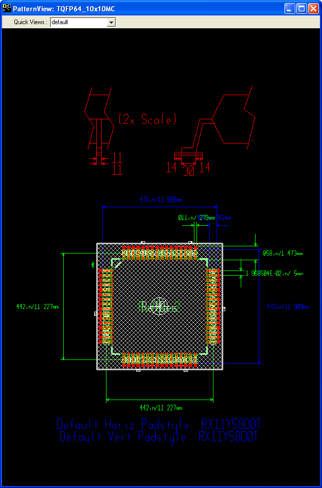
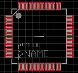
After your file is selected, the windows on either side of the main dialog will update to show what you’re working with. On the left, you can see the package; the combo box at the top allows you to select different views. On the right, you’ll see the symbol.
The views are initially cramped and hard to see, but though it isn’t obvious, you can zoom in. Just resize the window, right-click inside it to bring up the context menu, and select one of the zoom options. It also supports mouse-wheel zoom, but I don’t recommend using it; it confused my copy so badly that it crashed.
The program is also, unfortunately, somewhat buggy (bad VB app, remember?). It seems that if you close the viewers, you’re supposed to be able to use the unlabeled arrow buttons at the bottom to reopen them. It only actually works for the symbol viewer, so beware.
I don’t know that I’ll ever understand why people in this space can’t manage to build half-decent user interfaces…


Thanks Steve, this is very helpful. I’m having a problem, though with part names not showing up on the schematic. They import nicely into Eagle, but I am not able to change REFDES or TYPE. After clicking the info button, and the + on the component, a properties box pops up titled GATE. I am not able to select REFDES or TYPE. Any idea how I can change the REFDES to show the component in the schematic? I am using the free version of Eagle 6.2.
It sounds like you’re editing the wrong item; you’re in the device editor, which only allows you to edit the relationships between symbols and packages, not the symbols and packages themselves.
If you want to edit what appears in the schematic, look at the top tool bar; if you’re using the defaults, the fifth button from the left will select a package to edit, and the one to the right of it will select the symbol.
Hope this helps!
I got bit in the same way — I couldn’t edit or group as the earlier poster indicated.. After following your suggestion that fixed it for me! Thanks for the great help!
Pingback: Generate Any Microchip PIC Footprint For EAGLE | Macdweller | The Frogs blog
How do you enter Pin 1 Designator? I need the dot with dash for pin 1?