
Interlude: Innovation!
So I finish getting all the surface mount components on the board, and solder down the crystal as well. That’s basically it for the general components; all that’s left are the buttons and that godforsaken display. I still can’t believe I forgot to check the thing.
Now I’m stuck, though.
It’s basically built, but I don’t want to put the switches on unless the display will work – and I don’t know yet how to put the display on. Some quick testing shows that the circuitry appears to work (or at least, the processor is running), so there’s nothing stopping me if I can figure out how to make the display fit. I just have to figure out how.
(Side note: when I first got my hands on my Fluke 87V, I thought the frequency counter would be the most useless feature. Not so! Turns out, it’s actually quite handy for quick circuit checks. Probing the row lines showed a 20KHz signal, which meant that the processor was running. No oscilloscope necessary!)
So I enter head-scratch mode for a bit, and then my eyes fall on a pile of jumper wires sitting in front of the prototype. Hmmmmm, I think. Would that work? Those are, what, 22 gauge? They might just fit…
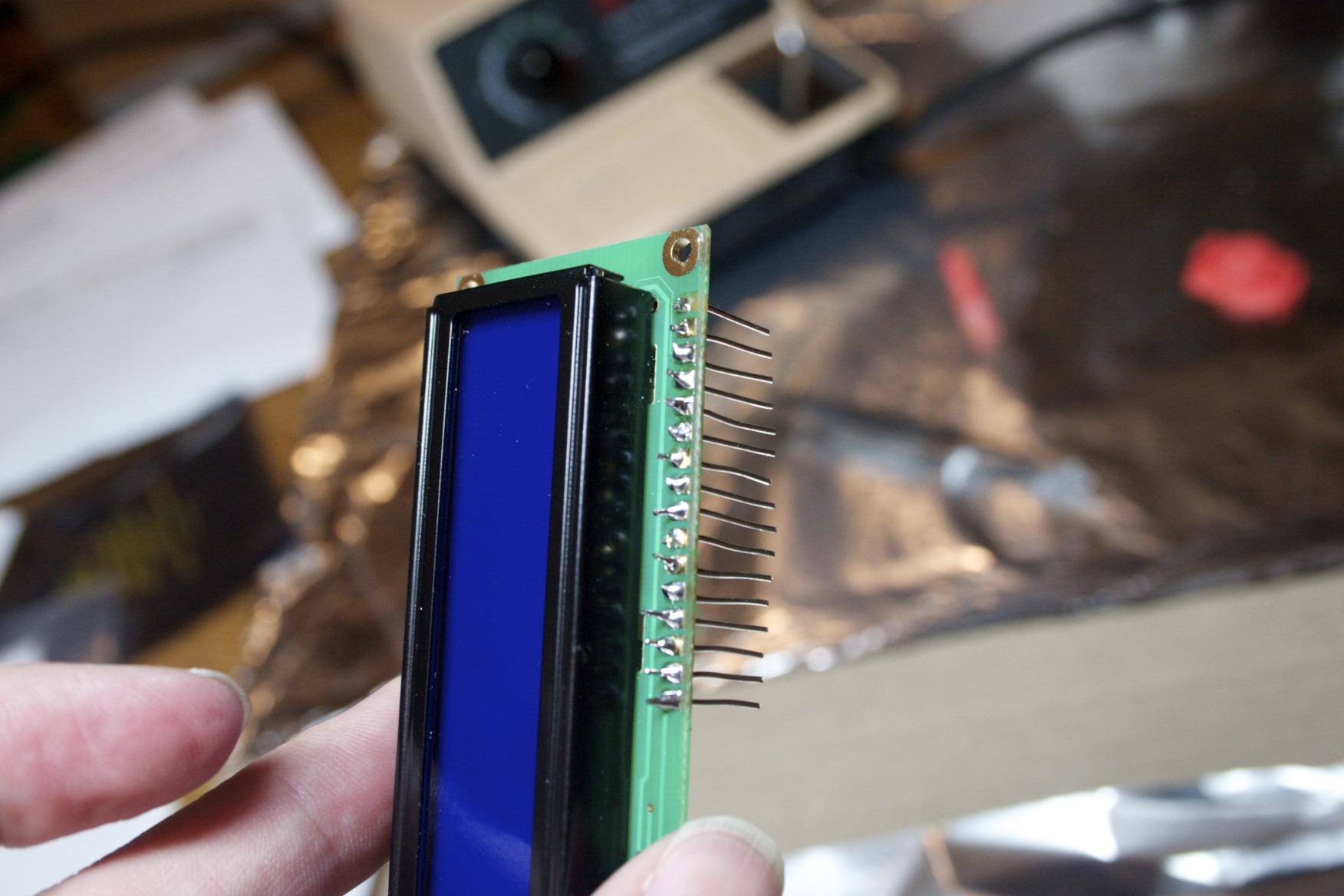
Looks a bit like a funky hi-tech comb, doesn't it?
And sure enough, they do.
And so ensues the tedious task of stripping down a bunch of pre-cut jumper wires (I didn’t have any other solid 22-gauge wire) and chopping ’em up into little bits. Now all I have to do is figure out how to get the already-soldered header out of the prototype’s display without destroying the thing. I have no desoldering equipment.
I tried that a couple of weeks back with solder wick, but it was a Really Bad IdeaTM. It resulted in a mangled display: a couple of pads pulled up, and solder down in the holes that’s impossible to get out without proper tools. I only had the two displays, one of which was toasty, so making that kind of error was right out.
But then, I think, what if that other display can be salvaged?
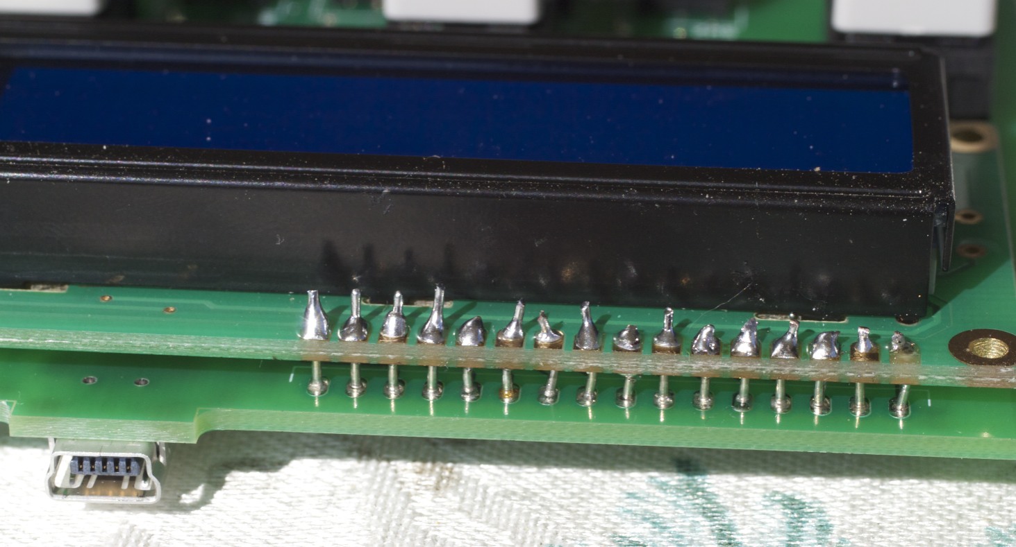
So I go spelunking in the parts bin and pull out the old display. I mean, I have flux now, right? This should be doable! Copious application of flux to the pads, load up the iron with solder, and use tweezers to shove my makeshift pins through the solder-filled holes while applying the iron.
Lo and behold: success! And a resurrected display that I thought was worthless, to boot: I plugged it into the breadboard (easier said than done), and it worked perfectly. Turns out, there were no traces connecting the pads I managed to destroy.
Step 4: First Run
Success! Not the prettiest job in the world, but it works.
Okay, so I have a display. After tangling with my makeshift header and managing to get it soldered down to the board, I go through and start putting switches down. This is the easy part; yeah, there’s some fifty-four pins to solder, but they’re all through-hole, which makes it trivial (and flux helped here, too).
That finished, I come to the realization that the thing is actually done. There are no more parts left. Everything’s soldered. Close examination shows that everything appears to have good joints, and nothing is out of place.
So I plugged it in.
I was actually pretty surprised; I figured it would probably blow up on me, but it didn’t. In fact, the results were extremely positive. The display came right up, and everything worked.
Well, almost everything.
The playing song happened to be unrated, and I noticed that the red 5-star button was flashing instead of the white 0-star button. That reminded me that I’d made some design decisions when I designed the PCB: specifically, I reversed the LED pins because it made for a cleaner board design. Okay, that’s an easy fix; edit platform.h and reset the pin assignments, recompile, flash it in, and all is good.
The only other issue was that the one-star button was generating a zero-star keypress event. This was something I’d seen before while tinkering with the values of the pull-down resistors on the prototype: if they were too large, the inputs wouldn’t settle fast enough, and you’d register incorrect key hits. It wasn’t all that surprising, really.
This is likely caused by a difference in parasitic capacitance in the design. I’d expect it to go the other way, but you never know with these things. I’m not an expert on PCB design, and have no idea how to calculate such things.
Fortunately, this is an easy problem to solve in firmware. Just add a 1µs delay after setting up the relevant row line, before reading the column inputs. The extra delay gives the circuit time to settle. At 24MHz, the PIC’s instruction cycle is about 170ns, which is just too fast for my chosen values.
Flash the new firmware, and the problem is solved.
4 Responses to TC: Surface Mount Madness