Step 4: Clean Up The Symbol
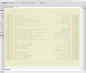
When you open the symbol, you may find that it’s unnecessarily wide, with lots of empty space in the middle. Solving this is simple; just group-select the right-hand side of the symbol (making sure to include both pins and wires), and move everything to the left. This may not seem necessary, but I prefer my symbols to be compact so I can fit more stuff on a schematic sheet.
Next, alter the text labels to work properly with EAGLE. First, click the info button (![]() ) and select the label titled REFDES. It should already be in layer 95 (Names), so just change the value to >NAME. Likewise, select the TYPE label, which should be on layer 96 (Values), and change set it to read >VALUE. You should also feel free to relocate the labels to wherever you want them.
) and select the label titled REFDES. It should already be in layer 95 (Names), so just change the value to >NAME. Likewise, select the TYPE label, which should be on layer 96 (Values), and change set it to read >VALUE. You should also feel free to relocate the labels to wherever you want them.
Next, you’ll notice that the names of any inverted signals are preceded with an asterisk instead of having the usual line over them. This is easily corrected: simply select the pin using the Name tool (![]() ) and edit the name. Instead of the asterisk, surround the signal name with bangs (*MCLR becomes !MCLR!, for example). Now you’ll have the expected line over the names of inverted signals.
) and edit the name. Instead of the asterisk, surround the signal name with bangs (*MCLR becomes !MCLR!, for example). Now you’ll have the expected line over the names of inverted signals.
The final step (which you can skip if you don’t care) is to go through and set the direction of each pin. They’re set to Passive by default, but you can do whatever you like with them. This is mostly used in ERC, for example to check if the power pins are connected to the correct supply.
Okay, now we have a workable symbol. What’s next?
Step 5: The Package
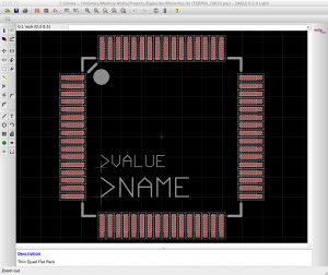
 The packages generated by Ultra Librarian are a complete mess. Oh, the pads and such are fine, but all the text labels are positioned right smack on top of each other in the middle of the part. You’ll have to manually move them and figure out what you want to do with them.
First things first, use the move tool to separate all the text out, ensuring that you can see all of it. My sample 16F1947 is a TQFP64, and came with no less than nine text labels (note that the asterisk that indicates the location of pin 1 is actually two labels; one on tDocu, and one on tPlace). Overkill much?
In my case, I removed everything except the VAL and RefDes2 labels. The former (on layer 51, tDocu) became >VALUE, and the latter (on layer 21, tPlace) became >NAME. In my workflow, tPlace is generally included in the silkscreen; plan accordingly for yours.
I didn’t like the asterisk next to pin 1, so I also swapped that out for my usual pin 1 indicator: a solid dot in the interior corner. While the symbol does have a slanted line there as an indicator, I find a largish dot much more obvious during assembly. Use whatever makes you happy.


Thanks Steve, this is very helpful. I’m having a problem, though with part names not showing up on the schematic. They import nicely into Eagle, but I am not able to change REFDES or TYPE. After clicking the info button, and the + on the component, a properties box pops up titled GATE. I am not able to select REFDES or TYPE. Any idea how I can change the REFDES to show the component in the schematic? I am using the free version of Eagle 6.2.
It sounds like you’re editing the wrong item; you’re in the device editor, which only allows you to edit the relationships between symbols and packages, not the symbols and packages themselves.
If you want to edit what appears in the schematic, look at the top tool bar; if you’re using the defaults, the fifth button from the left will select a package to edit, and the one to the right of it will select the symbol.
Hope this helps!
I got bit in the same way — I couldn’t edit or group as the earlier poster indicated.. After following your suggestion that fixed it for me! Thanks for the great help!
Pingback: Generate Any Microchip PIC Footprint For EAGLE | Macdweller | The Frogs blog
How do you enter Pin 1 Designator? I need the dot with dash for pin 1?