Step 2: Select Target Package and Options
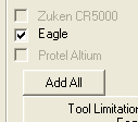
 On the left-hand side of the screen, you’ll see checkboxes for each supported CAD package. Make sure that EAGLE is the only one selected (unless, of course, you use something other than EAGLE; I don’t, so I can’t comment on support for other packages).
Next, you’ll need to set your output directory.
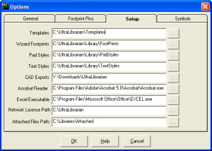
 Click the Configuration button on the right-hand side of the main window, and select the Setup tab. You’ll find there a list of directories, most of which you don’t care about; the only one we’re really interested in is the CAD Exports directory. Either enter your chosen output directory here, or click the ellipsis button to the right of the entry to choose one with a standard Windows file dialog.
You may want to tinker with the other settings in the configuration dialog, but I didn’t find it necessary.
Step 3: Generate Script and Import Into EAGLE
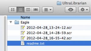
 Next, click the big “Export to Selected Tools” button. This will create a directory called “Eagle” in the export directory you specified in the previous step, in which it will place a new EAGLE-compatible script. This is what you’ll use to create your parts in your EAGLE library.
Note that the scripts are named only with the date and time they were generated (eg. 2012-04-28_14-28-59.scr). If you export multiple parts, you’ll need to pay attention, or perhaps rename them as they’re generated so you can tell them apart. You’ll also find a readme.txt in the directory; this contains instructions for EAGLE users (which, at least on the Mac, are slightly incorrect).
 And now, it’s time to import them into EAGLE.
Fortunately, it’s a straightforward process. Simply open your target library (or create a new one), select “Script…” from the File menu, and choose the script file that Ultra Librarian generated for you. When it finishes running, it should open the resulting device in the device editor. Easy, right?
Of course, nothing is perfect, so there’s still more to do.

Thanks Steve, this is very helpful. I’m having a problem, though with part names not showing up on the schematic. They import nicely into Eagle, but I am not able to change REFDES or TYPE. After clicking the info button, and the + on the component, a properties box pops up titled GATE. I am not able to select REFDES or TYPE. Any idea how I can change the REFDES to show the component in the schematic? I am using the free version of Eagle 6.2.
It sounds like you’re editing the wrong item; you’re in the device editor, which only allows you to edit the relationships between symbols and packages, not the symbols and packages themselves.
If you want to edit what appears in the schematic, look at the top tool bar; if you’re using the defaults, the fifth button from the left will select a package to edit, and the one to the right of it will select the symbol.
Hope this helps!
I got bit in the same way — I couldn’t edit or group as the earlier poster indicated.. After following your suggestion that fixed it for me! Thanks for the great help!
Pingback: Generate Any Microchip PIC Footprint For EAGLE | Macdweller | The Frogs blog
How do you enter Pin 1 Designator? I need the dot with dash for pin 1?