
Step 2: The Processor
I’ve read a lot of the tutorials out on the ‘net about drag soldering, and I’m actually excited about it. They make it look so easy! Just put some flux on the pins, add some solder to your iron, and swipe. Done!
It is not as easy as it looks.
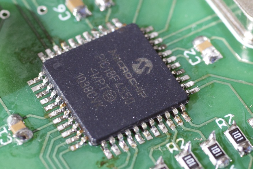
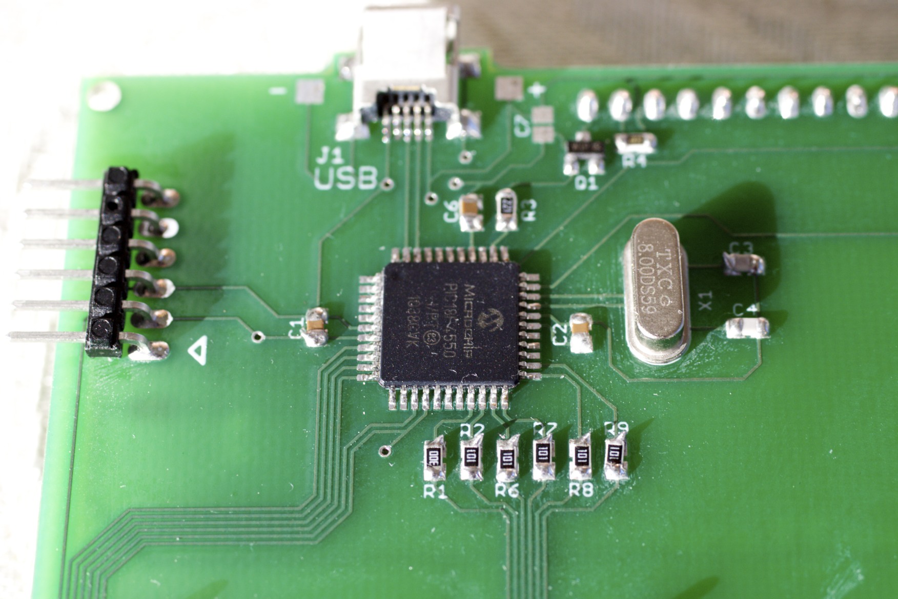
The completed PIC18F4550, before the board was cleaned.
Really, though, it’s not too bad, all things considered. While I did bridge half the pins on the chip, judicious application of solder wick took care of that fairly easily. It wasn’t the prettiest job on the planet, but it worked.
What did I do wrong? Probably two things: too much solder on the iron (all the more available for bridging), and dragging across the pins too quickly, not giving the solder enough time to flow. We’ll find out next time I have a QFP to solder.
In the end, however, I have a nice 44-pin QFP soldered to the board, and it only took half an hour (including a lot of time spent staring at it, trying to see if there were any bridges I missed. The pins are a lot smaller than they look in videos and pictures!).
Curious, I decide to put the ICSP header on the board and flash the firmware. Sure enough (and much to my surprise), it worked flawlessly the first time. I wasn’t even forced to ground RB5 for some reason; luck of the draw, I guess. I’d even designed jumper pads into the board for doing that, but it wasn’t necessary.
Step 3: Teeeny Leeetle Parts
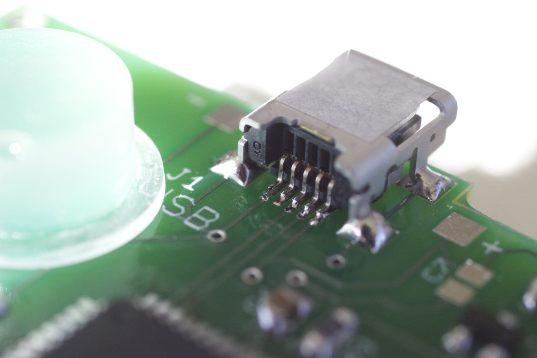
The USB Connector, all dressed up.
Now that I knew the processor worked and appeared to be soldered correctly, it was time to build the rest of it.
To be blunt, the QFP was the second-easiest part of the build (the easiest was the USB connector, surprisingly enough). The tiny discrete components, on the other hand, were rather annoying. They’re almost impossible to see with any clarity (I think I need one of those ring magnifiers), and that makes life difficult.
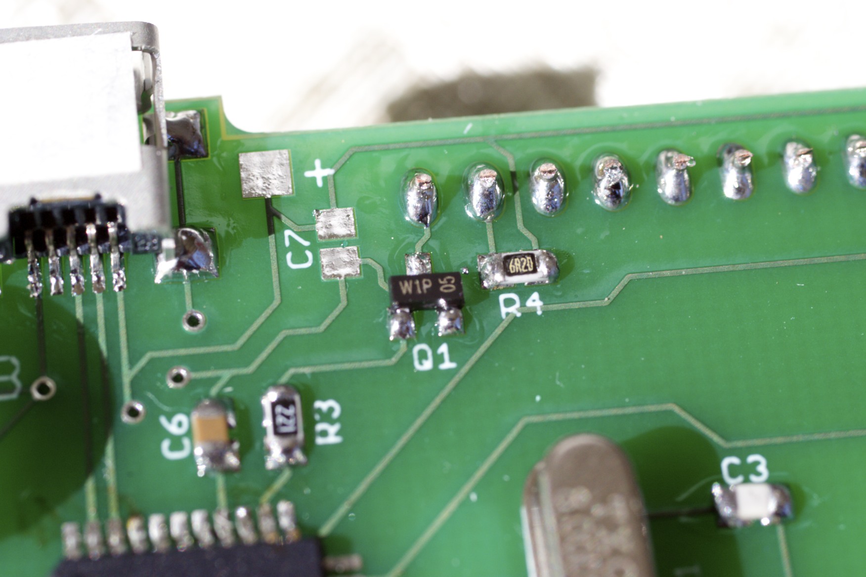
The low-pass D/A contrast control and display power switching transistor
Of course, before you ever get there, you realize just how difficult it is to coax the things out of their nice, comfy cut-tape homes. That stuff is not designed for manual extraction; it’s made for machines. I ended up using my tweezers to punch through the backing and push the components out the front.
I was kinda surprised I didn’t damage any of ’em. Anyone know a simpler way to deal with cut tape?
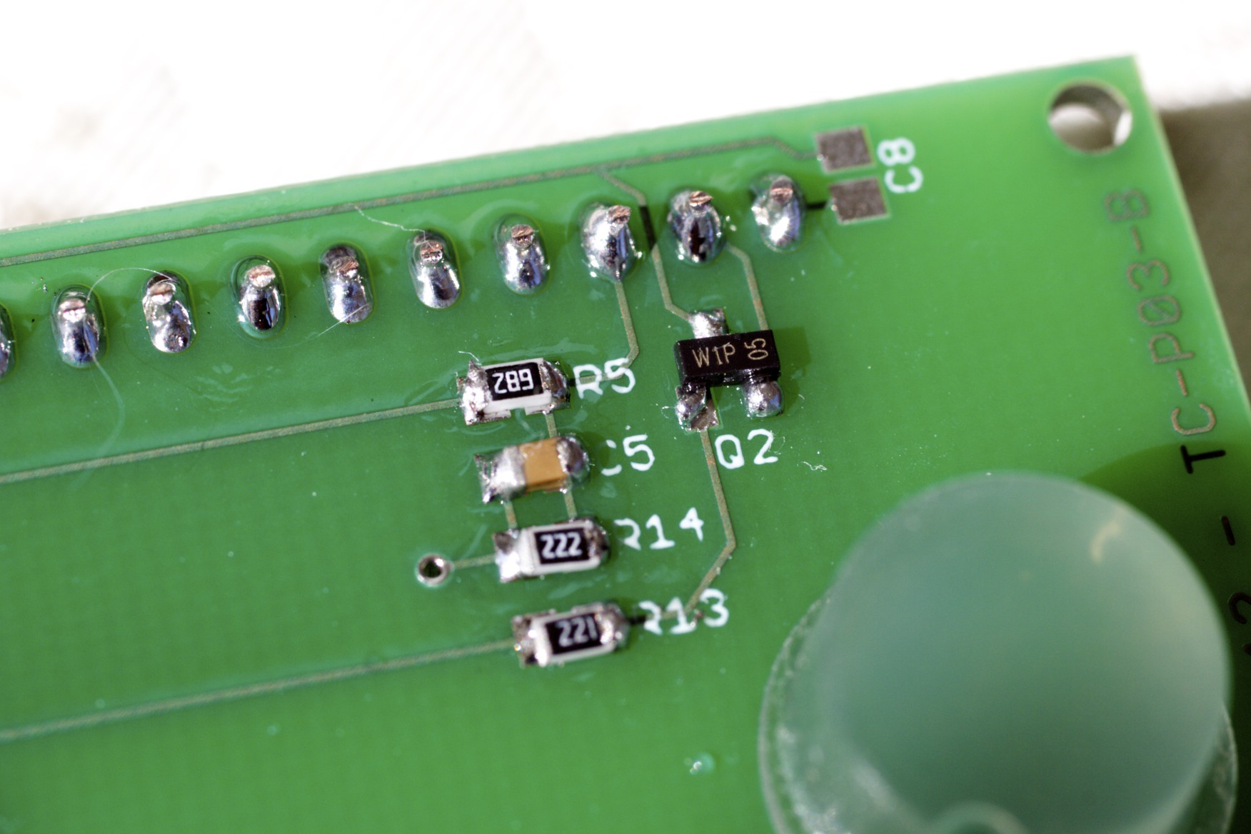
Backlight current limiting and PWM switching
The transistors were the worst of the lot. I made the mistake of tacking down the collector first, which is the sole pin on that side of the package. This resulted in the transistor lifting up on one side, and I had to try several times with each to get them reasonably flat on the board.
The other annoying problem was simply solder volume. I’ve never done 0805 components before, and given how hard they are to see, it’s hard to tell how much solder you’re applying. The result is a lot of very ugly blobs; the job doesn’t look professional at all. There’s probably a trick to it, but I don’t know what it is.
A slightly cleaner board. You can see the tails on the LED current limiting resistors; that's lack of flux for ya.
I also learned a very valuable lesson: flux is good stuff. Not only did the use of the ChipQuik flux produce the cleanest through-hole joints I’ve ever managed, but its absence was very visible on many of the discretes where I was too lazy to use it. Note to self: use flux on all solder joints from here on out.
Flux-core solder just won’t cut it anymore.
4 Responses to TC: Surface Mount Madness