
The Prototype
 Now I have my basic design completed, so I send off a couple of orders for the parts I don’t happen to have (including the MCU and some cheap pushbuttons for testing). If there’s one thing I hate, it’s waiting for parts. I miss having a nearby electronics supplier that has just about everything – and no, Fry’s Electronics most certainly does not count, at least where I live.
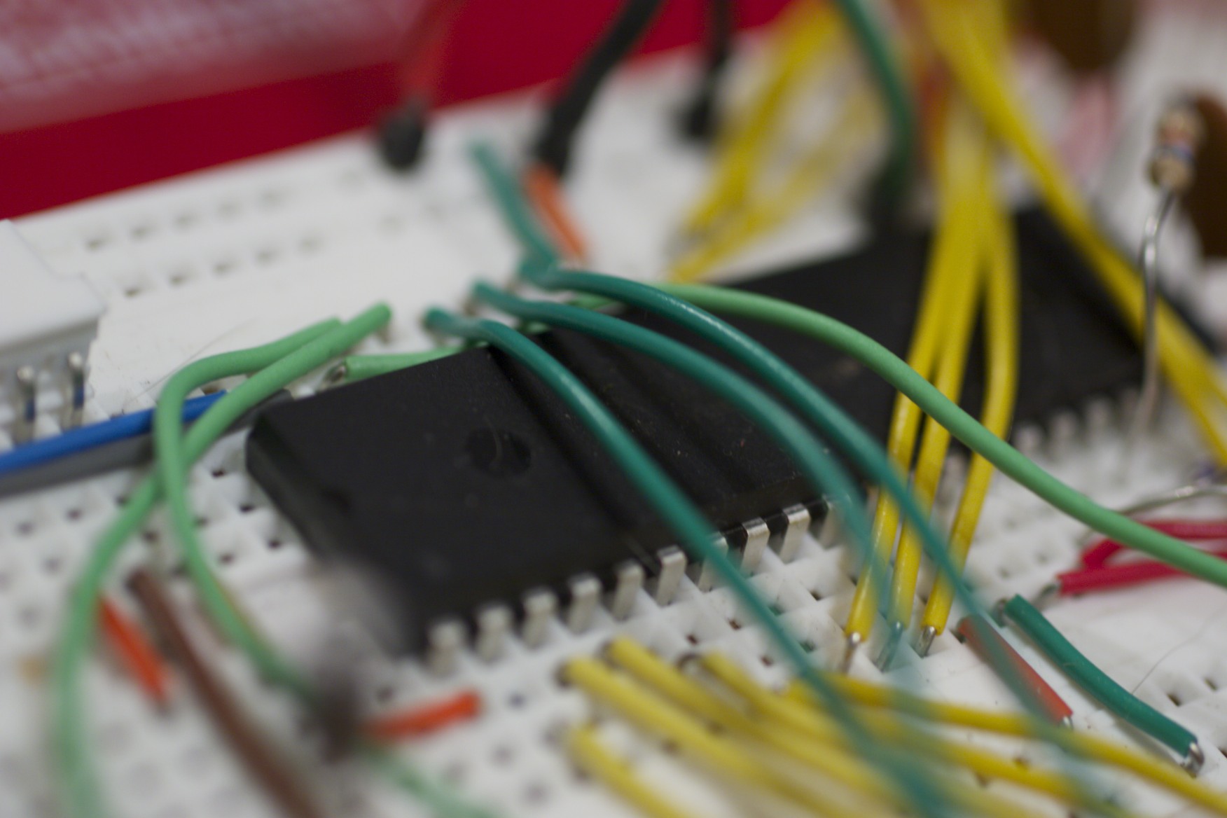
The most important parts arrive a couple days later, and I promptly dig out my trusty breadboard and start hacking away on the thing.
This is the entire reason I chose the 4550 over the more advanced parts Microchip offers. Availability of a DIP package is a major boon for someone who doesn’t have the cash to repeatedly send out for new PCB designs. Instead I can plug the chip into my breadboard and tinker to my heart’s content, only committing to copper when I have a reasonable expectation that it’s going to work.
My crystals not having arrived yet, I set up some simple test firmware that specifies the 8MHz internal oscillator and flashes the lights to verify that the chip is functional. I’ve also got a brand new PICKit2 that shipped with the chip order (my old programmer is an ancient parallel-port dongle, and it’s buried in storage somewhere at that), so I take some time to make that work on the Mac, which is easy enough. Finally ready to go, I plug in the PICKit2 and fire away…
…only to get bit by one of two discoveries I made about Microchip’s very strange default configuration settings on these things.
The 18F4550, like many other PICs, supports low-voltage programming (or LVP). This is enabled by default, which I suppose makes some sense. Unfortunately, this also means that the PGM pin (multiplexed with RB5 on this chip) must be grounded in order for standard programming methods to succeed. It’s not necessary once you turn the LVP configuration bits off, but until then…
The second discovery was that the dedicated ICSP pins on the 44-pin TQFP package are apparently disabled by default for some reason, which makes them pointless in my opinion, but that’s neither here nor there.
That was the only real hitch, though. With that resolved (and LVP now turned off so I don’t have to deal with it anymore), I happily flash my test firmware and give it a whirl. Works perfectly, of course; flashing lights aren’t that hard to accomplish on a PIC.
Liquid Crystal Dreams
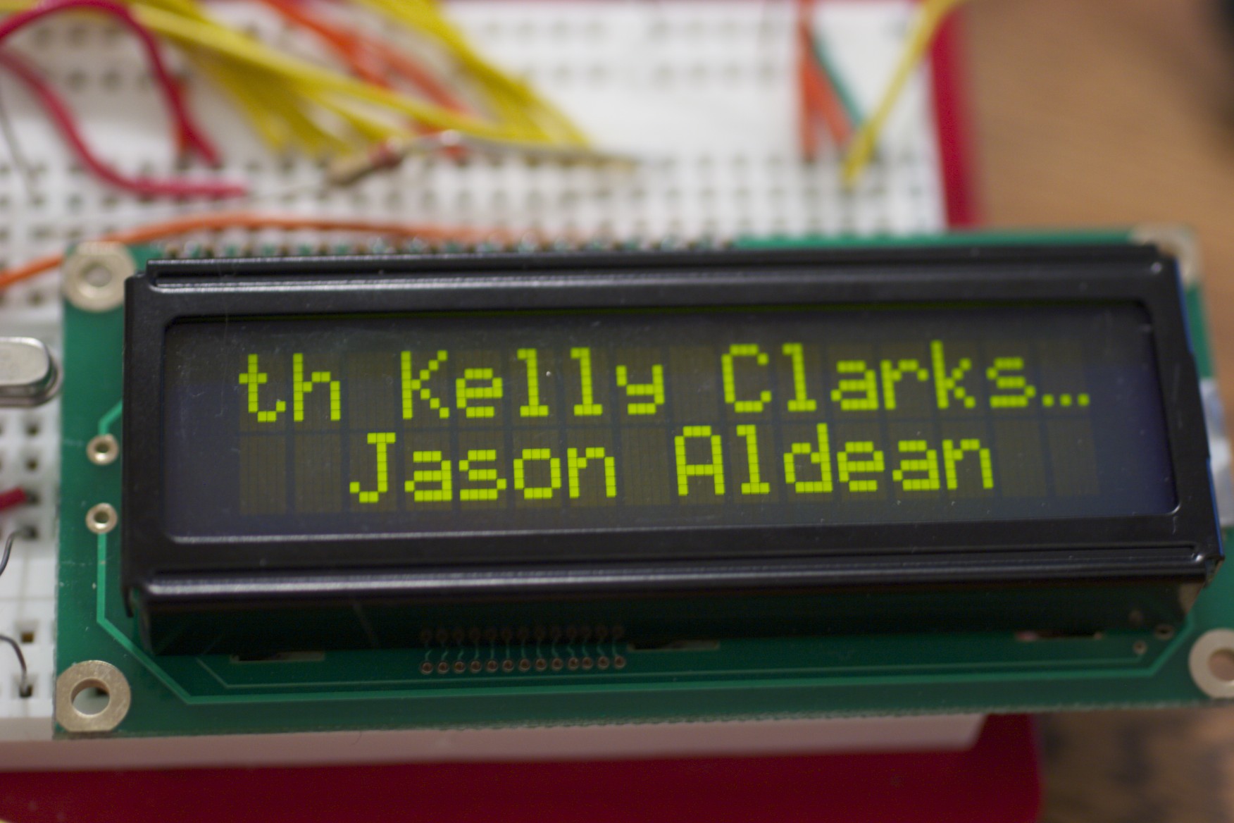
Now that I’ve verified that I still know how to set up and program the thing, I turn to the LCD, figuring it’ll come in handy for debugging. It’s connected on the full 8-bit bus since I have all these extra pins, and that makes talking to it a relatively simple task. Whip up a simple HD44780 display library, a bit of testing and debugging, and we’re good.
Of course, that was with the contrast hardwired.
 The software brightness control was easy enough; driving an LED backlight with a PWM signal is old hat. The only catch there is that the PIC can’t drive a 130mA backlight from an I/O pin, so I had to add a transistor to switch the high-current load. No big deal.
The contrast control, however, was another matter. At least on the display I have, Vo (pin 3) expects a variable voltage signal to determine the contrast. The “useful” range appears to be 0.2V to 1.7V, and I was left in a quandary because the MCU has no D/A converter. What to do?
More googling, and I find out that the solution is remarkably simple.
Low-pass filters are useful in surprising ways. In this case, all I had to do was add a simple RC low-pass filter to the output of the second PWM module to turn it into a reasonably effective D/A converter. Connect the output of that to the Vo pin, and I have contrast control.
That topic deserves a post all on its own; I spent a fair few hours making it work properly and learning a lot in the process. It’s a much cheaper solution than my other idea, which was to use a digital potentiometer. Tinkering with the filter values and figuring out how it all worked was kinda fun, too.
Pingback: Overbuilding an iTunes rating system - Hack a Day
Pingback: Overbuilding an iTunes rating system « Hackaday « Cool Internet Projects
Pingback: Overbuilding an iTunes rating system | ro-Stire
Pingback: Overbuilding an iTunes rating system | ro-Stire
nice post
Pingback: Overbuilding an iTunes rating system | CisforComputers
Pingback: Overbuilding an iTunes rating system » Geko Geek
I really appreciate a website that links its thumbnails to their full-size counterparts. It’s nice….
I hate being sent to some stupid image-sharing service to see the full size…. Ten clicks later…. Oh.. I’m not interested any more..!